Step 4: Properties
This step assigns hydraulic properties (hydraulic conductivity and porosity) to model elements.
- Click the "Properties" button to bring up the Properties Dialog Box.
- Select the “isotropic” or “anisotropic” option.
- Five sets of hydraulic conductivity (m/s) and porosity (%) values are available for assignment to model elements. Each set is represented by a color. Default values are initially provided, but you may alter any or all of these values in the edit boxes.
- Select a set of hydraulic conductivity and porosity values by clicking the color icon. The selected icon is indicated by a thick black frame.
- Click "OK" to close the dialog box.
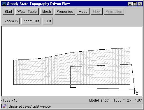
- Draw a polygon to enclose those elements you want to assign the selected property values. A polygon is drawn by clicking at its vertices. To finish drawing the polygon, double click the last vertex.
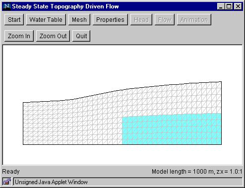
- The elements enclosed by the polygon are filled with the color you selected in the dialog box.


Additional zones with the same properties may be defined by drawing additional polygons. To specify a zone with different property values, click the "Properties" button again to bring up the dialog box and click on a different color icon. Then click "OK," draw a polygon as before. The newly selected elements now are filled with the new color. Drawing mistakes can be rectified by overdrawing with another zone. Any part of the mesh not covered by a polygon will have properties corresponding to the white color.
Go to Step 5
Back to Step 3
Return to Introduction